Installing Custom Computer
Some Dingo-O and Dingo-D robots may be sold without a main PC installed. If you have such a robot, you must provide your own PC for the robot.
This section explains the process of physically connecting your computer to Dingo. For OS and software installation, see Software Setup.
Note
For installing the OS on an Nvidia Jetson device, see Jetson Xavier AGX or Jetson Nano.
Supported PCs
Dingo has mounting hole patterns for standard mini-ITX motherboards and Nvidia Jetson Nano, NX, & Xavier AGX computers.
Note
Support for the Raspberry Pi 4 is coming at a future date. For now there are no official mounting solutions, but you may be able to create your own bracket for connecting the Rasperry Pi family of computers to Dingo.
We recommend the following minimum requirements for any custom PC installed in Dingo:
Note
Note that some accessories, such as 3d lidar, depth-sensing cameras, high-res cameras, and arms may have their own additional requirements that exceed these minimums.
CPU: Quad-core amd64 or arm64 at 1.4GHz or faster
RAM: 4GB
Storage: 64GB
At least 1 physical ethernet port
Mounting the PC
Mini-ITX format PCs, as well as the Nvidia Jetson family can be mounted directly to Dingo’s chassis using the provided mounting holes. We recommend using 20-30mm standoffs to ensure adequate clearance between the chassis and any ports on the board.
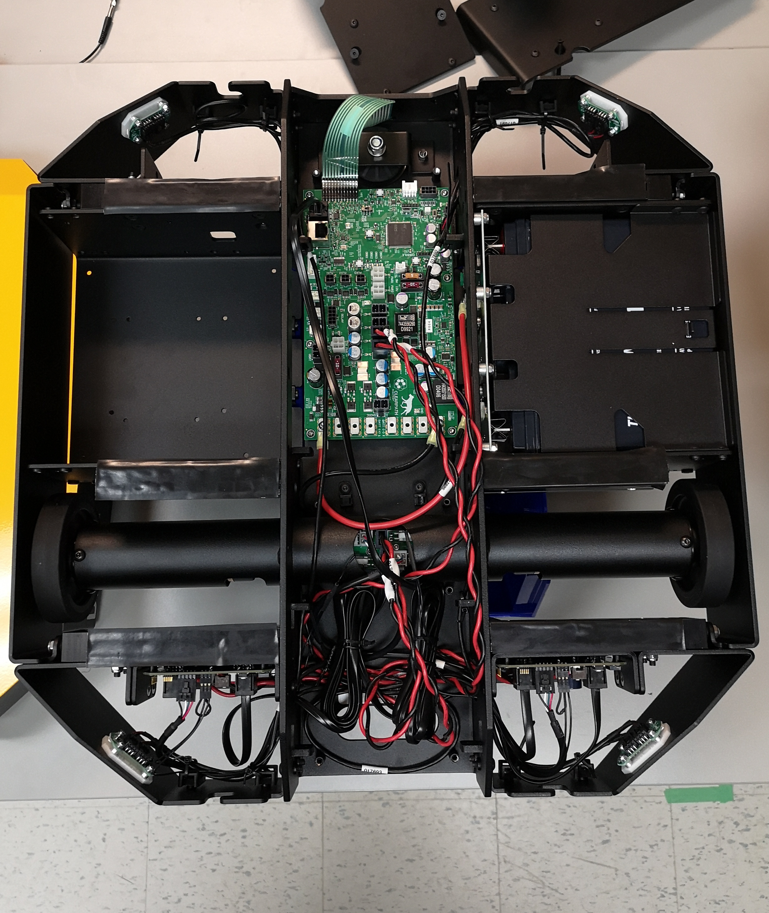
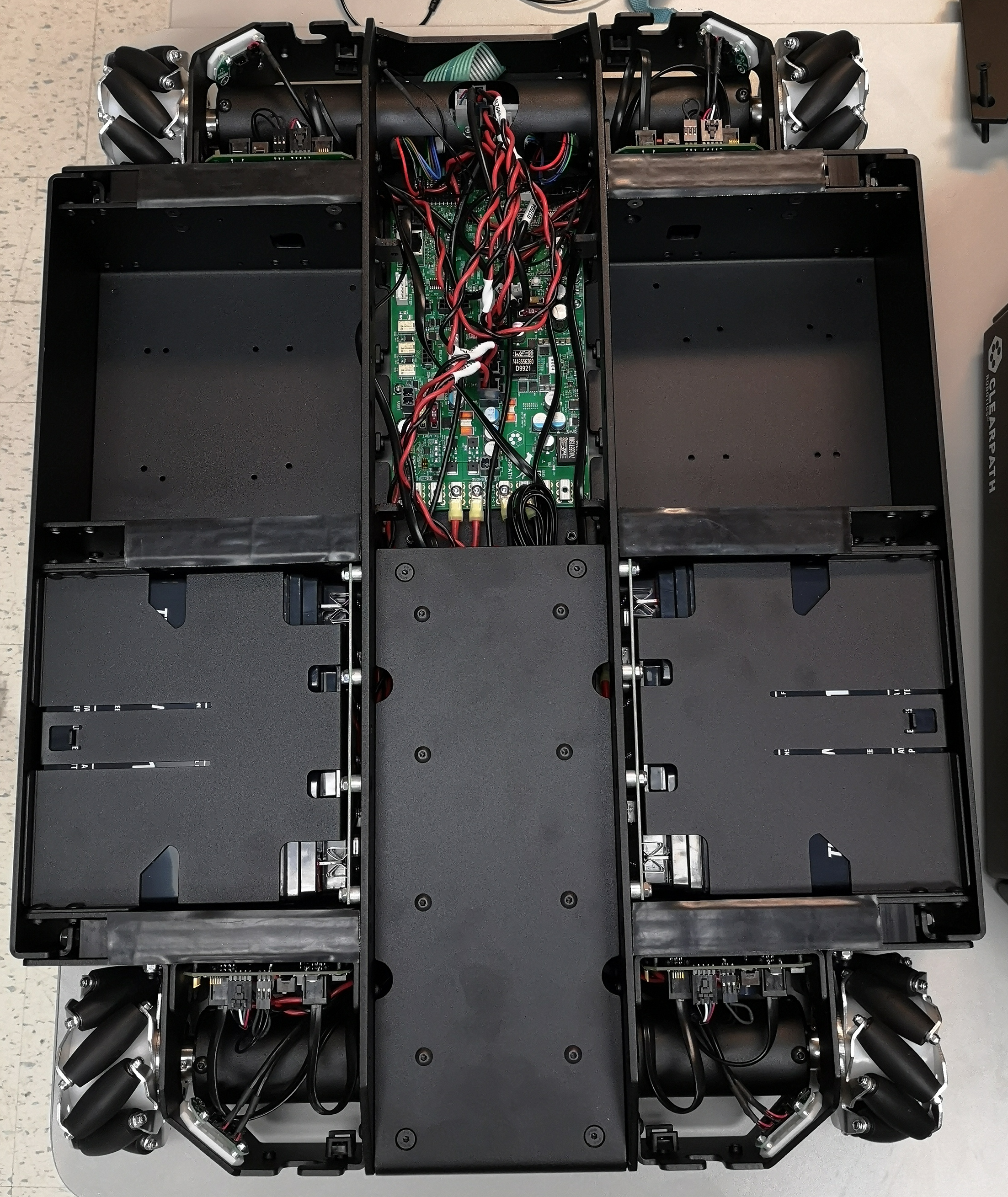
Dingo-D has a single payload bay for the computer, opposite the battery bay. Dingo-O has two computer bays, located in front of the two battery bays.
Small single-board PCs, such as the Raspberry Pi can be installed by either creating a custom 3d-printed bracket to make use of the existing mounting holes, or be affixed to the computer bay using adhesive on a third-party enclosure.
During OS installation you will need access to the USB, ethernet, and video ports of the PC. After installation the PC will need to be connected to the MCU via an ethernet cable.
Powering the PC
Dingo’s PC should be powered by connecting it directly to VBATT if it is tolerant to varying voltage (e.g.
a mini-ITX format PC with a pico-PSU), or to one of PWR1 or PWR1.
VBATT provides unregulated power drawn directly from Dingo’s batteries. At full charge this will be 12-14V, and
can be expected to decline steadily as the robot is used.
PWR1 and PWR2 can provide regulated 12V or 5V output by using the following pin mappings:
Pin # |
Pinout |
Current Limit |
|---|---|---|
1 |
12V |
10A total, 8A per pin |
2 |
5V |
5A |
3 |
gnd |
|
4 |
gnd |
Check your computer’s power requirements and connect its power to the appropriate power supply.
Note that the computer should not be connected to any of the AUX power supplies. These are intended to supply
power to accessories such as sensors and lightweight arms that require external power.
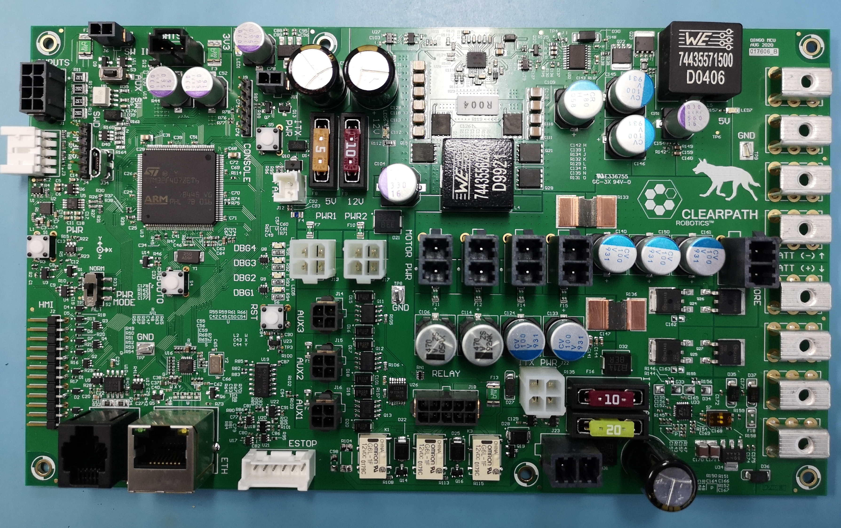
The image above shows Dingo’s MCU. PWR1 and PWR2 are the large white connectors in the middle. The 3 black
connectors below them are AUX1-3. VBATT is the large, black, 2-pin connector located near at the bottom, near
the 10A and 20A fuses.
Installing a network switch
Because many sensors use ethernet connectivity you may find it useful to install a small ethernet switch inside Dingo’s main center bay.
Power for the switch should be drawn from AUX2 or AUX3, as dictated by the switch’s input voltage (see above).