Simulating Dingo
Whether you actually have a Dingo robot or not, the Dingo simulator is a great way to get started with ROS robot development. In this tutorial, we will go through the basics of starting Gazebo and Rviz and how to drive your Dingo around.
Installation
To get started with the Dingo simulation, make sure you have a working ROS installation set up on your Ubuntu desktop, and install the Dingo-specific metapackages for desktop and simulation:
Note
Currently there are no released pre-built APT packages for Dingo; you must install Dingo packages from source.
mkdir -p ~/catkin_ws/src
cd ~/catkin_ws
catkin_init_workspace src
cd src
git clone https://github.com/dingo-cpr/dingo.git
git clone https://github.com/dingo-cpr/dingo_simulator.git
git clone https://github.com/dingo-cpr/dingo_desktop.git
cd ..
rosdep install --from-paths src --ignore-src
catkin_make
source devel/setup.bash
Launch Gazebo
Gazebo is the most common simulation tool used in ROS. Dingo’s model in Gazebo include reasonable approximations of its dynamics, including wheel slippage, skidding, and inertia. To launch simulated Dingo in a simple example world, run the following command:
roslaunch dingo_gazebo dingo_world.launch
You should see the following window appear, or something like it. You can adjust the camera angle by clicking and dragging while holding CTRL, ALT, or the shift key:
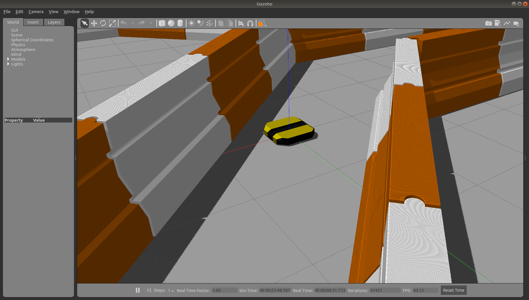
The window which you are looking at is the Gazebo Client. This window shows you the “true” state of the simulated world which the robot exists in. It communicates on the backend with the Gazebo Server, which is doing the heavy lifting of actually maintaining the simulated world. At the moment, you’re running both the client and server locally on your own machine, but some advanced users may choose to run heavy duty simulations on separate hardware and connect to them over the network.
Note that like Dingo itself, Dingo’s simulator comes in multiple flavours called configs. A common
one which you will need often is the front_laser config. If you close the Gazebo window, and then
CTRL-C out of the terminal process, you can re-launch the simulator with a specific config:
roslaunch dingo_gazebo dingo_world.launch config:=front_laser
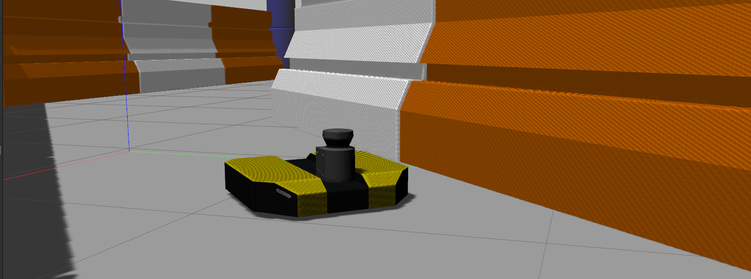
You should now see the simulator running with the simulated SICK LMS111 laser present:

Gazebo not only simulates the physical presence of the laser scanner, it also provides simulated data which reflects the robot’s surroundings in its simulated world. We will visualize the simulated laser scanner data shortly.
Launch rviz
The next tool we will encounter is rviz. Although superficially similar in appearance to Gazebo, rviz has a very different purpose— unlike Gazebo, which shows the reality of the simulated world, rviz shows the robot’s perception of its world, whether real or simulated. So while Gazebo won’t be used with your real Dingo, rviz is used with both.
Note
If you are working with a simulated robot you should leave Gazebo running and open a new terminal to launch rviz.
Make sure to run source devel/setup.bash when opening the new terminal.
You can using the following launch invocation to start rviz with a pre-cooked configuration suitable for visualizing any standard Dingo config:
roslaunch dingo_viz view_robot.launch
You should see rviz appear:
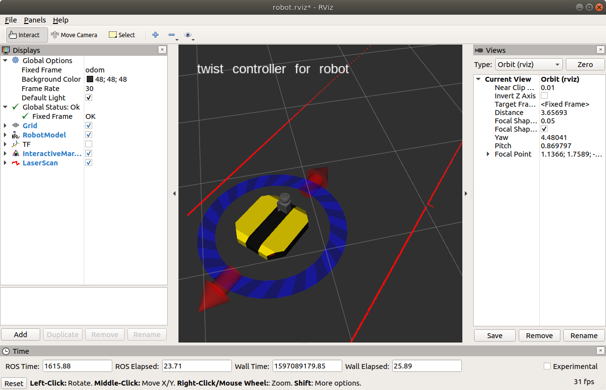
You can add the lidar data by clicking on the “Add” button in rviz, going to the “By Topic” tab, and choosing the
/front/scan topic. After this you should see red lines where the lidar detects the barriers, as shown in the image
above.
Driving Dingo-D
The default Dingo model is Dingo-D, equipped with a differential drive.
Rviz will also show Dingo’s interactive markers: the blue ring and red arrows. These are the simplest way to command your robot to move around. If you don’t see them in your rviz display, select the Interact tool from the top toolbar. You should see red arrows and a blue circle appear around the Dingo model.
Drag the red arrows in Rviz to move in the linear x and the blue circle to move in the angular z. Rviz shows you Dingo moving relative to its odometric frame, but it is also moving relative to the simulated world supplied by Gazebo. If you click over to the Gazebo window, you will see Dingo moving within its simulated world. Or, if you drive real Dingo using this method, it will have moved in the real world.
Once you start your own development, have your nodes send geometry_msgs/Twist commands to the cmd_vel
topic to drive Dingo, either real or simulated. This is the standard ROS interface to differential-drive and
holonomic ground vehicles.
Driving Dingo-O
The omni-directional Dingo-O model can be controlled in exactly the same way was Dingo-D in rviz. If you have the
DINGO_OMNI enviroment variable set to 1 then you will see two pairs of arrows:
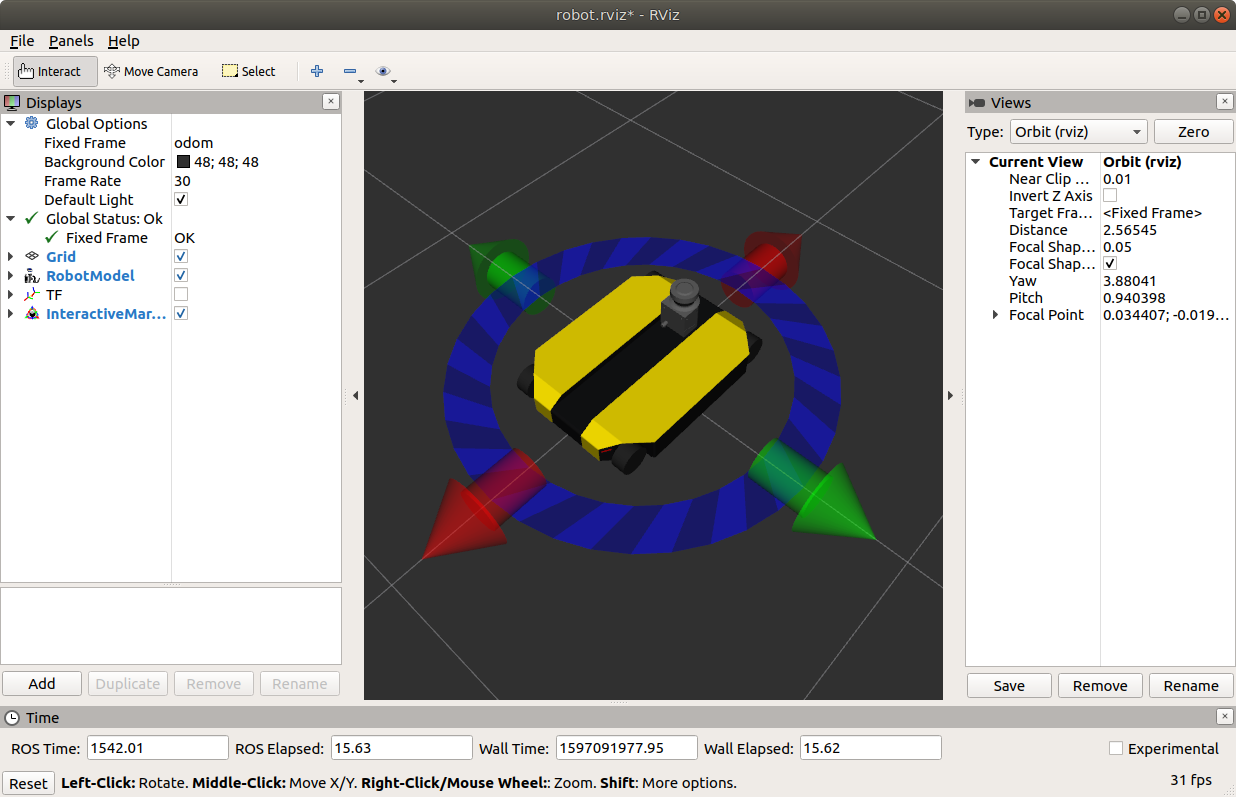
The red arrows and blue ring control the robot’s forward velocity and turning, as described above. The green arrows control the robot’s sideways movement.
Game Controllers and Gazebo
You can also use a game controller to drive your robot in Gazebo. To set up your computer for teleop using the game controller follow these steps:
Connect the controller to your PC.
Set the
DINGO_JOY_DEVenvironment variable to point to your game controller device. Normally this will be/dev/input/js0.Launch gazebo as described above.
Controls for driving the robot can be found in Driving Dingo. See Controller Pairing for additional information on how to pair your controller with your computer, or refer to the manufacturer’s instructions.
Visualizing Sensors
The rviz tool is capable of visualizing many common robotic sensors, as well as other data feeds which can give
us clues as to what the robot is doing and why. A great place to start with this is adding the
LaserScan plugin to visualize the laser scans being produced by the
simulated LMS111. In the left panel, click the “Add” button, then select the “Topics” tab, and then select the
front/scan topic:
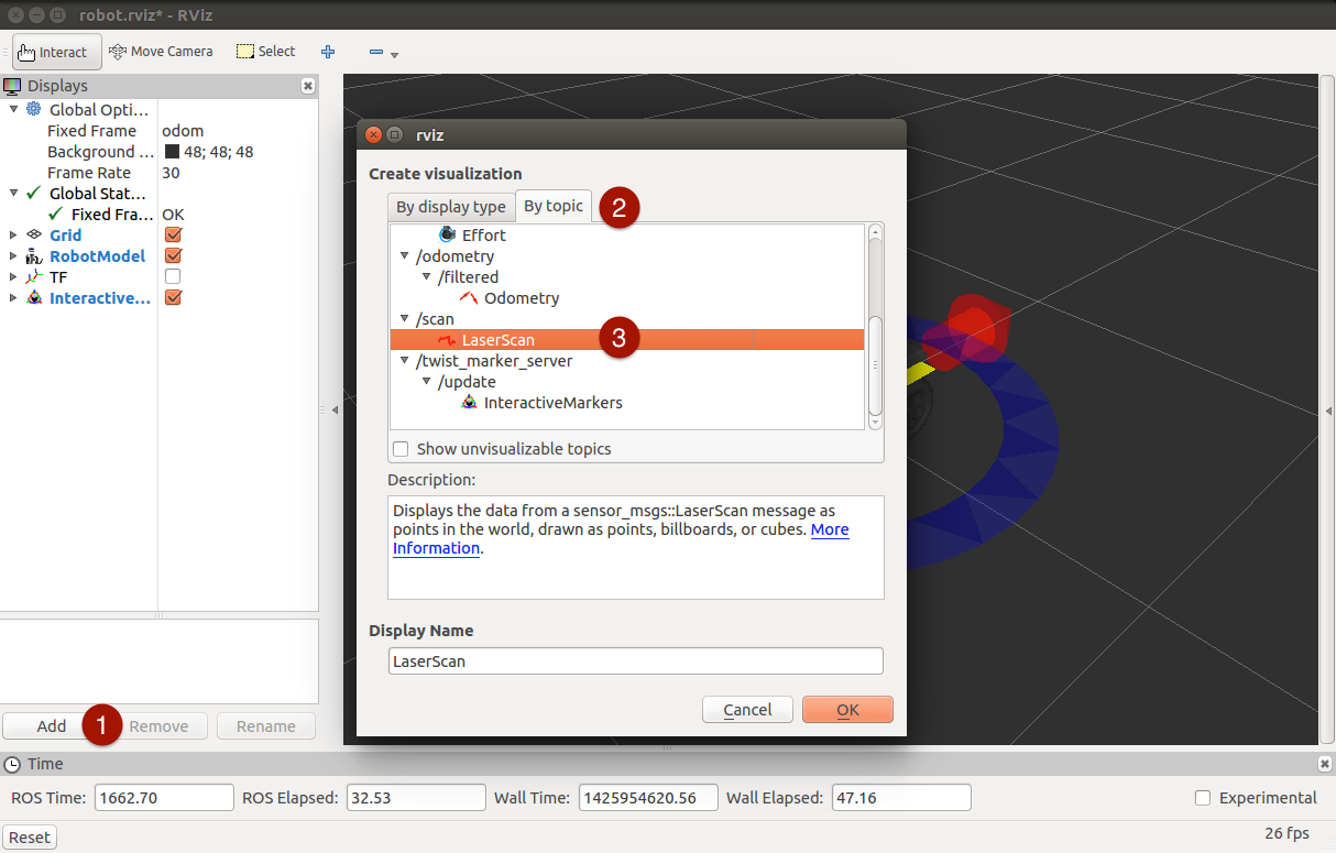
Click OK, and you should see laser scan points now visible in the rviz window, relative to the robot:
If you use the interactive markers to drive around, you’ll notice that the laser scan points move a little bit but generally stay where they are. This is the first step toward map making using gmapping, which is covered in the next tutorial, Navigating with Dingo.