Adding Payloads
Dingo’s base platform does not include any sensors by default, though Dingo can support a wide array of ROS-capable peripherals.
This section is not intended to be an exhaustive list of all supported payloads, but rather offer general guidance on how payloads should be connected to the robot.
Powering Payloads
Many payloads, such as sensors, arms, and network switches require external power. Dingo’s MCU is equipped with 3 auxiliary outputs which can be used to power these payloads:
AUX # |
Voltage |
Current Limit |
|---|---|---|
AUX1 |
12-14V (unregulated) |
20A |
AUX2 |
12V (regulated) |
10A total, 8A per pin |
AUX3 |
5V (regulated) |
5A |
AUX1 is connected directly to Dingo’s batteries, like VBATT. This will provide 12-14V when the batteries are
fully-charged, but can be expected to drop steadily as the robot is used. Payloads that are not tolerant to variable
input voltage should not be connected to AUX1.
Payloads may also be connected to PWR1 or PWR2:
Pin # |
Pinout |
Current Limit |
|---|---|---|
1 |
12V |
10A total, 8A per pin |
2 |
5V |
5A |
3 |
gnd |
|
4 |
gnd |
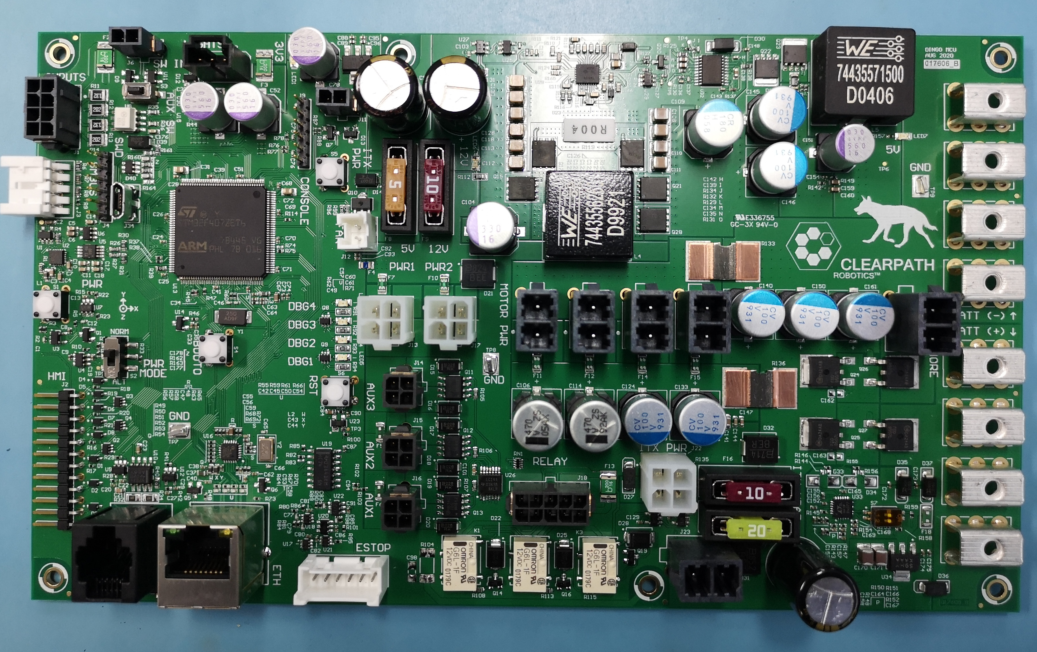
The image above shows Dingo’s MCU. PWR1 and PWR2 are the large white connectors in the middle. The 3 black
connectors below them are AUX1-3. VBATT is the large, black, 2-pin connector located near at the bottom, near
the 10A and 20A fuses.
To access the MCU, remove Dingo’s rear center channel cover. Note that there will be several cables connected already to provide power to the motors, computer, and any other payloads already installed.
Enabling AUX Power
By default the 3 AUX power outputs are disabled. To enable them you must publish a message to the /mcu/aux_output
topic. This topic accepts a single integer used as a bit-mask to enable/disable each of the 3 AUX power outputs:
AUX # |
Bit |
|---|---|
1 |
0 |
2 |
1 |
3 |
2 |
To turn on one or more AUX outputs, simply publish a single message with the appropriate bits set to 1 to turn the output on and 0 to turn it off. For example:
# turn off all AUX output
# Binary: 00000000 = Decimal: 0
rostopic pub /mcu/aux_output std_msgs/UInt8 "data: 0"

# turn on all AUX output
# Binary: 00000111 = Decimal: 7
rostopic pub /mcu/aux_output std_msgs/UInt8 "data: 7"

# turn off 2 & 3, turn on 1
# Binary: 00000001 = Decimal: 1
rostopic pub /mcu/aux_output std_msgs/UInt8 "data: 1"

# turn on 2 & 3, turn off 1
# Binary: 00000110 = Decimal: 6
rostopic pub /mcu/aux_output std_msgs/UInt8 "data: 6"
Mounting Payloads
The center channel covers of Dingo-O and Dingo-D feature multiple mounting points for payloads. Each mounting point is a square 80mm mount with 4 M5 threaded holes in the corners. These mounting points are accessible through Dingo’s URDF:
Link (front to back) |
Dingo-D |
Dingo-O |
|---|---|---|
|
Yes |
Yes |
|
Yes |
Yes |
|
Yes |
Yes |
|
No |
Yes |
|
Yes |
Yes |
|
Yes |
Yes |
|
Yes |
Yes |
See dingo_description for more information about Dingo’s URDF
Mobile Manipulation
Dingo can be equipped with a Kinova Gen3 Lite arm to provide mobile manipulation. Please see Mobile Manipulation for more information on how to install and configure the arm.