
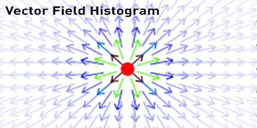
Local path planning is an integral part of robotics and there are numerous methods for achieving this. One such method is the Vector Field Histogram (VFH). The main idea behind this method of navigation is that through the robot’s sensors, it is able to detect objects and gaps. It is able to localize these things by their angle relative to the robot and their distance from the robot. In the implementation we have here, the sensor is of the LaserScan type, as defined by ROS. The specific sensors that output this data type were a Velodyne HDL-32e LIDAR in real world testing and a Hokuyo LIDAR in simulation. Because of random noise, a simple average smoother was added to the program to take five sets of scans and average them out to try to eliminate some errors in the scan. All code was written for ROS Fuerte using the “rosbuild” system.
Identifying Gaps and Objects
To identify the gaps and objects within a field of view there were multiple methods that were tested and modified. The final product that this testing provided was a two part system that would look for abrupt changes in the distances of the laserscan as well as a gradient change between the points. The latter indicated an “Edge” while the former indicated a “Corner”, both of which contain data within structs in the program. These two identifiers were used to determine where the objects and gaps were, how viable they were, and whether or not the robot should move towards them.
Finding the right direction
Depending on the directionality of the edge, whether the next point was farther or closer than the previous, allowed for the categorization of whether there was an object or gap present. There is a pairing edges which is needed for a viable gap. There was a possibility of repeated types of gaps (two starting edges of an object, etc.) and this issue was dealt with by knowing that there needed to be an end edge after a start edge and vice versa, thus the redundant ones are eliminated from the program. Whether a gap is passable by the robot is determined by using the edges to find the average distance (from the robot) of the two edges’ points as compared to the average distance of all the points between the two edges’ points. If the average of all the points is sufficiently higher than the average of just the the edges’ points, then that means there is a gap. The size of the gap is also calculated using the cosine law to find whether it is wide enough for the robot to fit through. What is left is an array of edges that will be paired and filtered to determine if they are viable paths.
The data being passed to the edge detection function is limited to the desired threshold which can be set by dynamic reconfigure. This limits the number of false positives that are produced by the program, as the farther away points have a lower quality than the closer points. This also limits the number of headings to those in the immediate area. All points beyond the threshold are set to zero.
[code]
void VFH::edge_detector(std::vector &input_array)
{
std::vector all_edges;
std::vector zeroed_array;
//Zeros the out of bounds members
for(int i = 0; i < input_array.size(); i++) { if(input_array[i] > turn_threshold) {
zeroed_array.push_back(0);
}
else {
//within_threshold set here
zeroed_array.push_back(input_array[i]);
}
}
//Finds abrupt chnage in the data and puts it in the first tier of edges
for (int i = 1; i < (zeroed_array.size() – 1); i++) {
POI temp;
if ((zeroed_array[i+1] – zeroed_array[i]) < -0.5) { temp.distance = zeroed_array[i]; temp.angle = i * increment; temp.type = 0; all_edges.push_back(temp); } else if (zeroed_array[i+1] – zeroed_array[i] > 0.5) {
temp.distance = input_array[i+1];
temp.angle = (i+1) * increment;
temp.type = 1;
all_edges.push_back(temp);
}
}
//Used for trouble shooting, not necessary for regular running
/*
gnuplot_cmd(hdl, “plot ‘-‘ using 1:2 n”);
for(int i = 0; i < zeroed_array.size(); i++) { double x = i * increment; double y = zeroed_array[i]; gnuplot_cmd(hdl,”%f %f n”, x, y); } gnuplot_cmd(hdl, “e n”); */ //Checks to see if area behind edge pair is suitable if(all_edges.size() > 1) {
passable_depth(all_edges, input_array, edge_list);
}
//Removes redundant edges from edge_list
if (edge_list.size() > 0) {
std::vector::iterator i = edge_list.begin();
while (i != (edge_list.end()-1)) {
if ((i+1)->type == i->type) {
if (i->type == 0) {
edge_list.erase(i+1);
}
else if (i->type == 1) {
i = edge_list.erase(i);
}
}
else {
i++;
}
}
}
//Displays first tier of edges
if(edge_list.size() > 0) {
for (int k = 0; k < edge_list.size(); k++) {
//ROS_INFO(“Angle: %f, Distance: %f, Type: %d”, edge_list[k].angle, edge_list[k].distance, edge_list[k].type);
}
//Places the proper heading into gaps if viable
passable_width(edge_list);
}
all_edges.clear();
zeroed_array.clear();
}
[/code]
How the laserscan perceives edges
The image below shows an example of what the laserscan would “see”. The edges would be identified as the abrupt change from an object to a zero value. Note the drop off around the x-axis at 1, this extra edge would be eliminated by the function as it is a redundant edge.
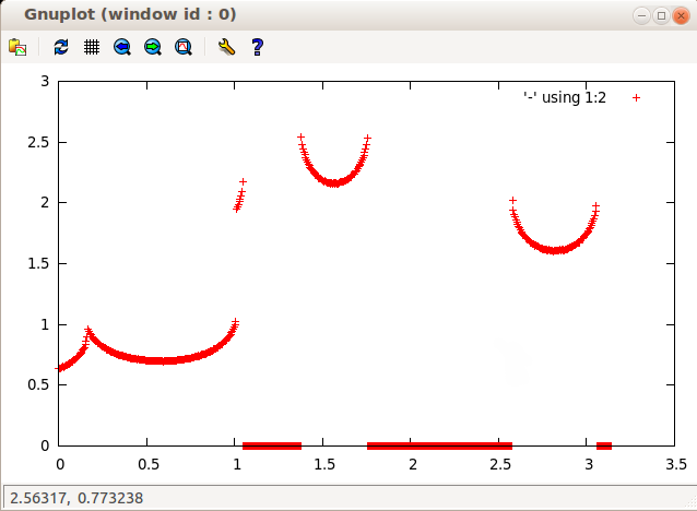
Laserscan Perception
Like the edge detection mentioned above, the corner detector is used to identify objects and empty space. However the corner detection uses the gradient between the points of data to determine if there are corners. It was decided to add the corner detector as the edge detector was failing to detect door frame edges or certain sharp turns. It mainly serves as a backup to the edge detector. To get the gradients of the robot’s view, the algorithm uses the distance and angle of each point to get an x,y pair. It then finds the “slope” or gradient to the next point in the series. All the gradients between a point and the next are stored as a data struct in a std::vector.
Corner detector vs. edge detector
To pick out the general trend of a sharp curve, the gradient information is averaged around each point, that is at point ‘a’, 10 gradients before and after it are compared to see if they are differing enough to be considered relevant, this is then repeated for a+1 and so on. To determine if the corners are passable (that is they have a gap between them) the same method for the edge detector is used. The corner detector is currently used when the edge detector does not produce any paths and the shortest distance within the alert threshold.
[code]
void VFH::corner_detector(std::vector &input_array)
{
//Gradient threshold is 70 degrees
double gradient_threshold = 1.22;
//Sets up x and y coordinates for gradient as well as creates vector of all gradients between all the points in the laserscan
for (int i = 0; i < (input_array.size() – 1); i++) {
double x0 = input_array[i] * cos(i*increment);
double y0 = input_array[i] * sin(i*increment);
double x1 = input_array[i+1] * cos((i+1)*increment);
double y1 = input_array[i+1] * sin((i+1)*increment);
Vector temp;
temp.x = x1 – x0;
temp.y = y1 – y0;
temp.i = i;
temp.distance = input_array[i];
temp.slope = fabs(atan2(temp.y,temp.x));
gradients.push_back(temp);
}
//Temporary arrays to store sets of corners
std::vector first_tier;
std::vector second_tier;
double grad_ave_a = 0;
double grad_ave_b = 0;
int k = 10;
//Find the average gradient over span of 20 points for each point in Laserscan
while (k < (gradients.size() – 10)) {
for (int j = -10; j < 10; j++) {
if(j < 0) grad_ave_a +=gradients[k+j].slope;
else grad_ave_b +=gradients[k+j].slope;
}
grad_ave_a = grad_ave_a/10;
grad_ave_b = grad_ave_b/10;
if((fabs(grad_ave_a – grad_ave_b) > gradient_threshold) && (gradients[k].distance < turn_threshold)) {
POI temp;
temp.angle = gradients[k].i*increment;
temp.distance = gradients[k].distance;
temp.type = 1;
first_tier.push_back(temp);
}
k++;
}
//There must be 2 corners to proceed. Will determine is the area between the corners is clear behind it
if(first_tier.size() >= 2) {
passable_depth(first_tier, input_array, second_tier);
}
//Will add the way points of the corners to the viable paths
if(second_tier.size() >= 2) {
passable_width(second_tier);
}
gradients.clear();
first_tier.clear();
second_tier.clear();
}
[/code]
The following images show how the corner detector segments data. Each arrow represents the gradients in between laserscan points and the red dot shows where the comparison would take place at this specific iteration. About this point the gradients before and after are averaged and compared, in the first instance, a corner would be detected whereas in the second it would not since the change is not above the threshold of around 70 degrees (1.22 radians).
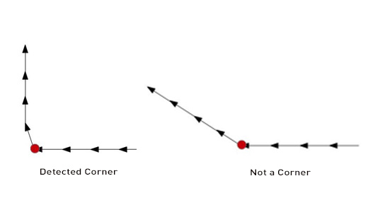
How corner detector segments data
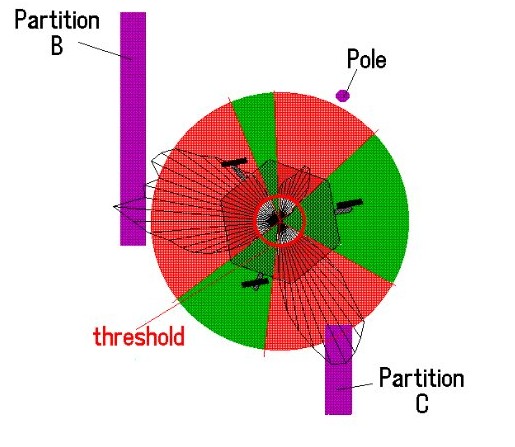
The program is designed to weigh the angle of the heading (from centre) along with the distance to the area corresponding to the heading (distance of the laser scan at the heading angle). The robot will want to move to a heading closer to the centre and as far away as possible.
Large space and set environments
The VFH works well for controlling the robot in large spaces with set environments. It’s important to note, however, that because of the edge and corner pairing process, it may not avoid an obstacle that comes into the frame immediately and very close. Thus, if there is something within the alert threshold of the robot, a process will be called that used the distance and angle of the close object to determine in it is within the forward path of the robot. If it is the robot, it will turn away from it until it is no longer in the forward path. The higher level controllers will then take over.
Headings for the robot are displayed in Rviz as green spheres. This is done by taking the angle and distance of the heading and mapping it to Cartesian coordinates. The x and y coordinates are then set to a marker (type) and broadcast as a marker_array. Rviz can then display this information as the viable paths of the robot.
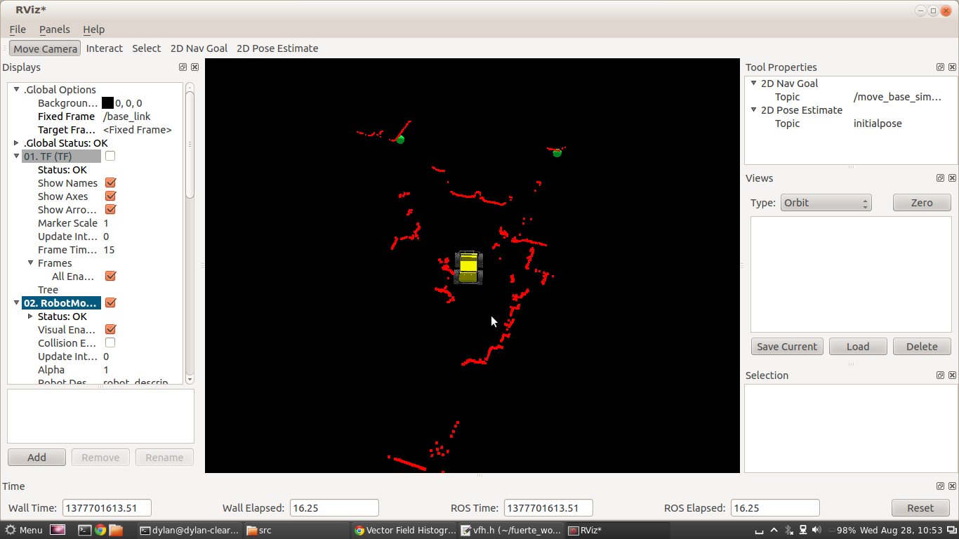
Rviz screenshot
The path that the robot will take to the given heading is determined by the angle to centre. The angular velocity decreases as the heading approaches the centre line of the robot whereas the linear velocity increases as the heading approaches the centre line. These velocities are scaled using the “angular_max” and “linear_vel” parameters that can be reconfigured while the program is running and set with the launch file.